Second Receiver for Yaesu FT1000MP MarkV
Bringing true second receive capability to the stock transceiver.makarov.ca
Subreceiver BPF controller for Yaesu FT1000MP Mark V
Building a independent second receiver channel for the lovely MarkV
Yaesu FT1000MP series transceivers have a second receiver that can only work on the same band with the main receiver. This is because the second receiver, or Sub Receiver, shares the same front-end bandpass filter with the main receiver. Making the Sub Receiver front-end independent from the main one has been a dream for many MarkV owners for a long time, both casual surfers and contesters. Adding a true second receiver for many happy MarkV owners could make it the Dream Radio. The project presented on this page has information on modifying a MarkV Field for a true dual receive. It then will be possible to use the main and Sub Receiver on two different bands simultaneously and mix the audio from the two channels in different ways. This is a unique project and you will not find this information anywhere else on the Net.
Components of the Mod
To enable True dual receive and seamlessly integrate it with the radio, three main components are needed: a custom made Sub BPF Controller, a separate Sub Receiver BPF filter (several are described in this article, but only one is needed), and a small signal switch to connect the second receiver input to the Sub BPF in Dual RX mode and to the existing circuit when in TX mode to keep the stock MONI (TX signal monitoring) feature. The following diagram represents the proposed changes in the architecture.
 |
The new components introduced by the mod are the Sub BPF, Sub BPF Controller, and the switch. They are described in details in the following sections in this article.
The Controller
The main problem with the existing second receiver channel is that no band information is available on the existing hardware interface in MarkV/Field to select the band filters. Only the main receiver band information is interfaced through one of the back panel connectors. Therefore, out of the box it is not possible to build a band decoder for the Sub Receiver channel to control a external front-end BPF for it.
This information is available though via the CAT computer interface. However, a computer would have to be connected to the transceiver all of the time then, which is not always convenient (also some people hate CAT), and the operator would have to deal with switching delays in the software polling the transceiver. Because the Sub Receiver is also used to monitor the TX signal when in MONI mode, and because the Sub Receiver input has to be muted when the transceiver is in TX, no delay in switching is acceptable for the Sub Receiver BPF. The Sub BPF Controller described here decodes the Sub Receiver band information in real time by monitoring control codes transmitted on the system bus, and generates needed signals to switch the second receiver input between the second BPF and the MONI circuit as required by the operating modes. No computer/CAT is needed, the Sub BPF Controller is completely autonomic. When complemented with a BPF as described further in this article, this results in a standalone transceiver with two independent receiving channels which normally would only be available in more expensive radios.
The board has a Microchip microcontroller that listens on the system bus for commands sent to the Sub Receiver frequency synthesizer during operation on the Sub Receiver, and transcodes them into the 4-bit binary code that represents the Sub Receiver band data. The data can then be used to automatically select the right bandpass filter.
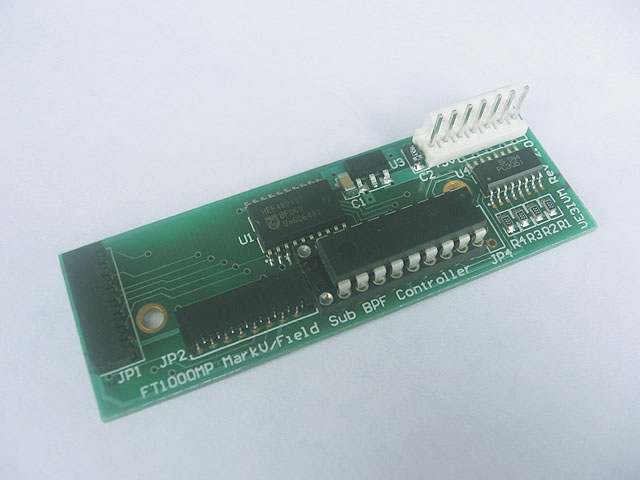
Fig. 1. The Controller board for the Sub receiver.
The Sub BPF Controller board has dimensions 3x1'' (76x25mm) and easily installs inside the transceiver. It has only a few components and consumes very little current. The microcontroller does not require a clock crystal, and generates no detectable RFI. The board is mounted in the bottom far right corner of the transceiver as shown in the following picture.
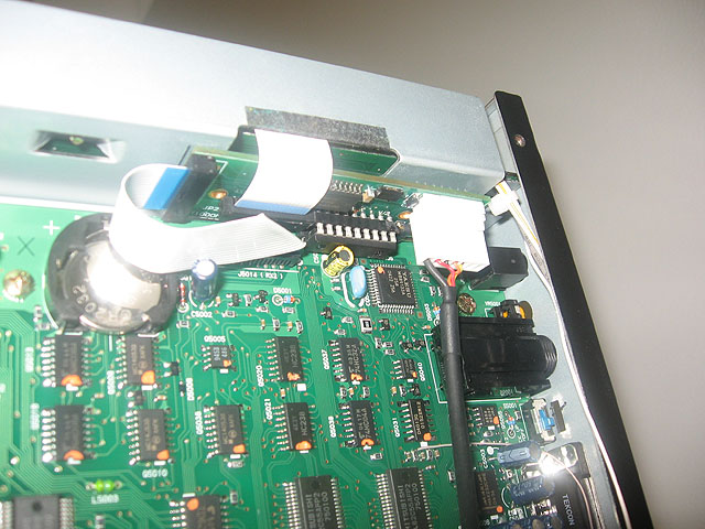
Fig.2. The transceiver bottom view. The Controller board is shown mounted in the top right corner of the picture, by the back panel.
To install the board, the flat cable coming out of the RX2 unit is disconnected from the J5014 connector (marking per the MarkV Field model. The base FT1000MP and MarkV may have this connector under a different designator) and connected to the Sub BPF Controller board, then the flat cable coming out of the Sub BPF Controller board (left side of it in the above picture) is connected to J5014. No soldering is required. It is a very neat setup.
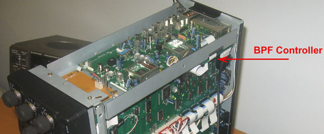
Fig.3. Position of the Sub BPF Controller board. Zoom out view.
The output of the Controller board is 4-bit binary code from 0 to 15, which can be used to control up to 15 band filters. The output is isolated from the transceiver internal circuit via a Darlington optocoupler with open collector capable of handling up to 60mA current. This gives freedom in connecting the Controller to a BPF mounted locally inside the transceiver, or run a fairly long control line to a external switchable BPF. Further in this article examples of the real setup are presented for both options.
The Sub Receiver band data decoded with the Sub BPF Controller can be used to control actual band filters that have electronic control via RF IC switches or relays. The filter banks that have 3- or 4-line binary control interface with built-in binary code decoder can be connected directly to the Sub BPF Controller. The filter banks that have individual control lines one per filter require a additional binary decoder to convert 4-bit binary data to the individual control line signals.
WB6DHW General Coverage BPF
This 6-bank BPF is recommended for general RX or casual surfing because it has wide band filters that contiguously cover frequencies from 1.5 to 30MHz. The filter has a 3-bit digital interface and can be controlled by the Sub BPF Controller directly. Also, this filter is very compact because it uses SMT components and because of its small size can be installed inside a MarkV Field as shown in one of the photos below in this article. The RF IC switches inside the filter consume very little power, so in this project the filter is powered from the Sub BPF Controller that has a voltage regulator built-in. This is a very compact setup because no external cabling is required outside of the transceiver, and it provides general coverage RX capability to the Sub Receiver.
For information on building this BPF please visit WB6DHW's WEB site. From there you can purchase boards and download the Parts List (BOM).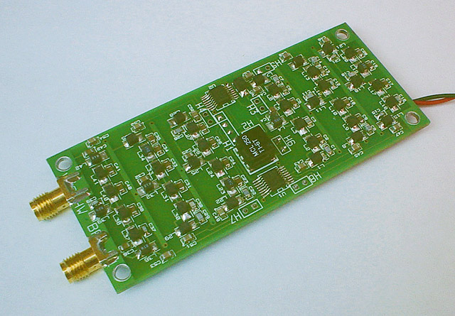
Fig.4. Assembled WB6DHW BPF board top view. I added two SMA connectors and soldered two pieces of the RG316 coax to the input and output of the filter.
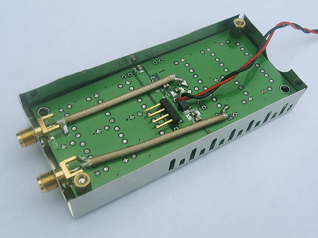
Fig.5. Assembled WB6DHW BPF board bottom view. The BPF is mounted in a shielding box.
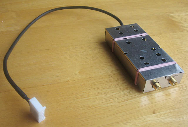
Fig.6. Finished BPF for the MarkV Sub Receiver.
Frequency coverage provided by the WB6DHW BPF. Apparently because the filter bins are wide and the filter uses standard SMT component values, there is 2 to 3dB ripple in the passbands. But in general isolation between the filter bins looks OK up to at least 60dB. There is some insignificant leakage above 30MHz.
As mentioned earlier, this BPF is good for general coverage, as it provides RX2 with the possibility of contiguous tuning from 1.5 to 30MHz. For contesting this filter may be not the best choice because the filter bins are too wide and strong signals from adjacent bands can cause interference.
When none of the filter banks is selected, measured isolation between input and output of the BPF (from the antenna) is better than 90dB. So if the filter is deactivated during TX (none of the filter banks selected), the RX2 input in the transceiver will be protected. Because this BPF uses fast silicon switches, break-in CW TX can easily be accommodated. This filter is completely quiet because there are no mechanical parts in it.
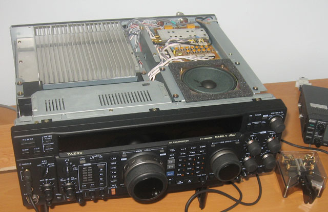
Fig.7. Completed Dual Receiver setup. The Sub Receiver BPF can be seen in the far right corner of the transceiver.
A surplus 6-Band BPF
This is a surplus 6-cell BPF covering general Ham bands. The filter has relay switched cells and requires individual control lines for each cell. In order to be used in this project, an additional decoder was needed to translate the Sub BPF Controller 4-bit binary code into the decimal code. I built this decoder on a vero board in the same external box with the BPF using a 74HC154N demultiplexor IC (4 to 16 line one), two 7407 non-inverting buffers, and a 7805 voltage regulator which converts the +13.8V from the radio to 5V to power the decoder circuit. the 7407's open collector outputs drive the filter cells relays and a string of LEDs connected that indicate the status of each cell.
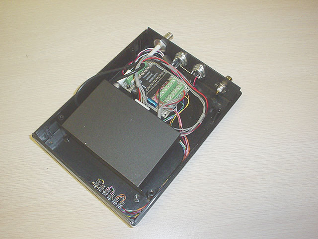
Fig.8. The 6-cell BPF mounted in a plastic enclosure. Open box view. The 4 to 16 lines add-on decoder board can be seen by the back panel behind the interface connectors. The black metal box in the middle is the BPF.
For this BPF I used a plastic enclosure from PacTec (Manufacturer P/N LH57-130-000-K, Mouser P/N 616-74216) with the LEDs mounted on the front panel as shown in the following picture.
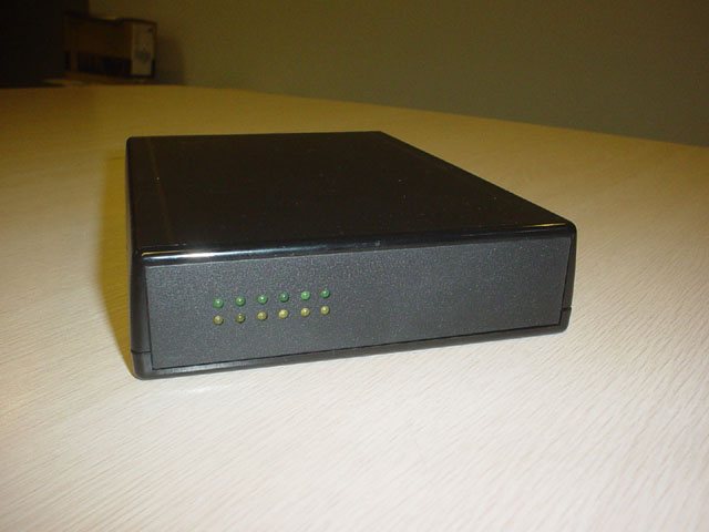
Fig.9. Surplus 6-cell BPF mounted in a box. Front view.
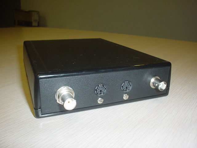
Fig.10. Surplus 6-cell BPF mounted in a box. Back view.
The back panel of this external BPF has two RF BNC type connectors for the antenna input and BPF band filtered output, and two mini-DIN connectors for the Sub BPF Controller control line and +7...15V external power line. To power the box, I used the MarkV's +13.8V power phono type connector located at the back of the radio. In this configuration the BPF is powered on and off with the radio.

I'd think other BPFs which cover the WARC bands can also be used. I do not have one to try but I expect it to work with the Sub BPF Controller without a problem. A 9-cell filter would probably make the best choice out of the BPFs presented in this article in terms of cost/efficiency ratio for the purpose of having HAM bands on the MarkV second receiver.
Yaesu BPF-1 General Coverage BPF
Yaesu used to produce a optional BPF filter (called BPF-1) for the FT1000D second receiver. It is a 11-cell BPF with a 4-line digital control interface and built-in 3-step attenuator. I have tried this filter in my dual receive setup and I was very happy with the results.
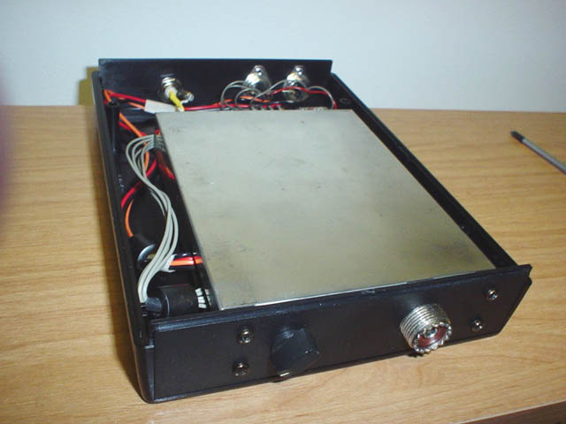
Fig.11. Yaesu BPF-1 mounted in a box. Open box front view. The stock front panel was removed from the BPF before it was mounted using the black screws from the removed panel. The panel then served as a template to mark the holes to be drilled in the plastic box side panel.
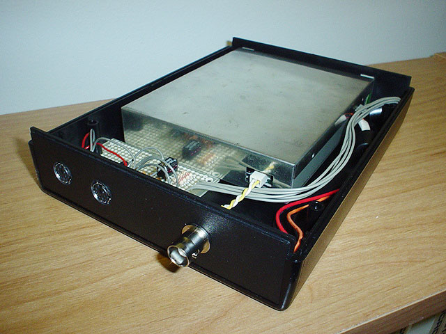
Fig.12. Yaesu BPF-1 mounted in a box. Open box back view.
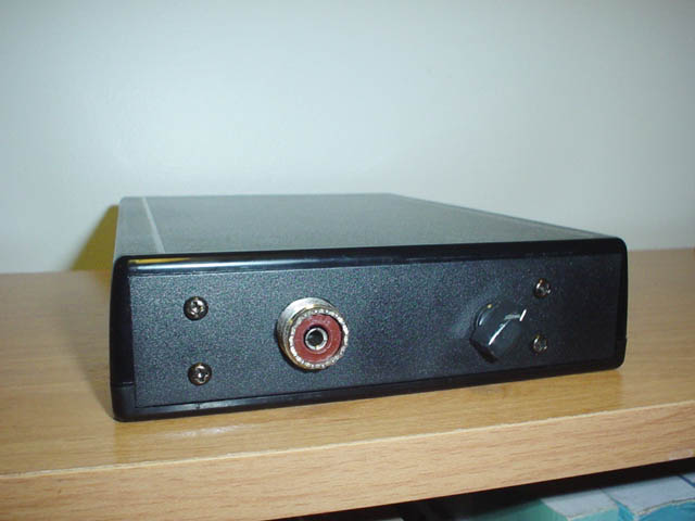
Fig.13. Yaesu BPF-1 mounted in a box. Front view.
Frequency coverage provided by the Yaesu BPF-1. This filter has 11 cells that generously overlap in frequency. For clarity not all cells are shown in this picture, there is more that overlap with the ones shown. This filter covers frequency range from 0.12 to 30MHz and can be used for general RX and HAM bands. The frequency bins selection is a bit more granular than for the ones in the Main Receiver BPF inside the radio.
Note that the 0.5 to 2MHz cell shows too much of a loss probably because I accidentally turned the 6dB attenuator switch on when I was measuring that cell. I do not have this filter anymore and can not repeat the measurement, but would think you should expect this cell top to be 6dB better unless Yaesu made this cell more lossy on purpose, or the filter that I measured was defective.
Overall the BPF-1 is a decent filter with a built-in attenuator and would have been the winner in this project if only it was available in the aftermarket. Unfortunately Yaesu discontinued it few years ago and it is very hard to find these days. I borrowed mine from a friend for evaluation and had to return it after I measured and tried it. If you find one, just grab it and run if you want to repeat this project. This filter has a 4-line binary control interface and can be switched directly by the Sub BPF Controller described in this article.
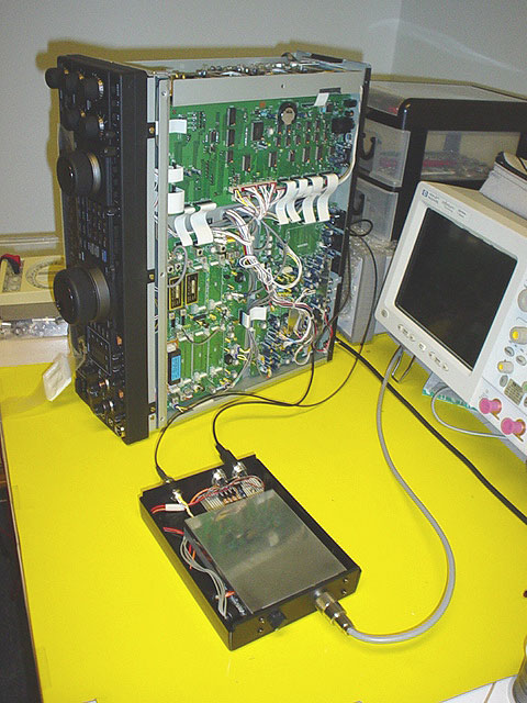
Fig.14. Yaesu BPF-1 connectivity setup.
Two cables can be seen connected to the radio. One is the 4-line control cable from the Sub BPF Controller, the second one is a RG174 coax supplying the RF filtered output to RX2 unit in the transceiver. Not shown is a power cable that connects to the +13.8V Phono connector on the back panel of the radio. The gray coaxial cable connected to the front panel of the BPF-1 comes from the second receiver antenna.
The BPF-1 has a built-in 3-step attenuator that can be controlled either using the switch on the filter's front panel, or electronically via a two line interface that enables 6dB and 12dB attenuation cells. Having a attenuator is an advantage of this filter over the other ones described in this article. If an other band filter is used, it may be a good idea to add an attenuator to it.
Because with either of the Sub Receiver BPFs described here the Sub Receiver channel becomes a independent receiver, its S-Meter can be enabled and will work independently from the main S-meter, measuring signals strength in the RX2 channel as shown in the following picture.
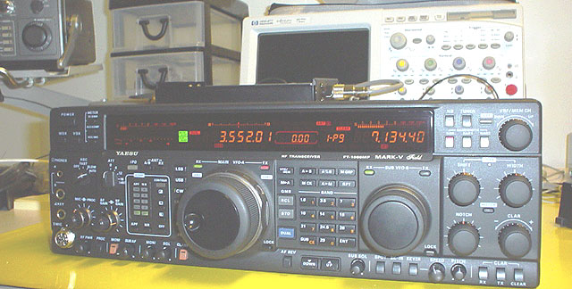
Fig.15. Sub Receiver operation with Yaesu BPF-1 external BPF. You can see the Sub Receiver working on the 40-meter band and its S-Meter now operating independently from the Main one, which is working on the 80m band. This was not possible to have with the stock transceiver.
Sub Receiver input switching circuit
In FT1000MP series radios the Sub Receiver channel is also used to monitor the TX signal during transmit when the MONI switch was activated. In order for the Sub BPF circuit not to affect this function, the RX2 input must be switched from the Sub BPF output back to the original circuit which is a feed coming out of the Main Receiver channel. Here is how it normally works in the transceiver: when MONI is enabled, a small portion of the TX signal is routed to the RX2 input, and the central processor in the transceiver sends a command to the Sub Receiver frequency synthesizer to switch to the transceiver TX frequency. If this link to RX2 input is not restored and the transceiver is in MONI mode, it will produce a distorted audio in the Sub Receiver channel.
In this project the proper RX2 input routing was realized using a small signal SPDT 5V relay activated during TX by the Sub BPF Controller. The pole contact of the relay was connected to the RX2 input via a coaxial cable. The normally open contact of the relay was connected to the Sub BPF output, and the normally closed contact - to the existing coaxial link from the Main receiver. When MONI is active during TX, the Sub BPF Controller engages the relay and closes the MONI signal loop. At the same time the Sub BPF Controller deactivates the Sub BPF antenna input, and that additionally isolates the RX2 input from the Sub BPF.
Conclusion
Having two independent receivers opens new capabilities for casual browsing, contesting and experimenting. The MarkV can now receive on two separate bands. When paired with my other mod, the VFO Sync one, the MP gets true stereo reception capability when both VFOs are tuned in sync and two physically separated antennas are used, the best if they have different polarization. I am not sure if this capability even exists in any of the latest multi-$$$ radios. In the literature this sometime may be called the "diversity reception", but I would call it "stereo reception", since for a true diversity reception two completely identical receivers are needed. This is not the case with either of FT1000 line transceiver, where the sub receiver differs from the main one in schematics and filtering, though their VFOs seem to be phase locked. Regardless, the stereo mode opens a huge field for experimenting with 2-receiver reception, from a basic audio base enhancement for casual surfing the bands to sophisticated combination of filters/EDSP/sideband settings to produce new enjoyable listening experience. "Flat" sounds become distinctive as if they come from different directions, especially with some intentional frequency shift between the VFOs introduced using the clarifier knob.
Downloads
| | Digikey BOM for the WB6DHW BPF | This is a ready to upload parts list to create a order on Digikey. Digikey does not stock Minicircuits parts, so the Minicircuits transformer has to be purchased separately from Minicircuits or wound in shack. |
In case you have questions, please feel free to email me at the address below.
Contact:  miv@makarov.ca